What you will learn
Validate a simulated high-level reflex interface while retaining the autopilot stabilization loop.
Before you begin: Robotics: estimation, planning & control; Spiking neural networks
Begin with forces and frames
A quadrotor changes motion by changing forces and torques. In an ideal level hover, total upward thrust balances weight. Roll, pitch and yaw describe orientation, but numerical commands depend on a documented coordinate convention. Motor and propeller behavior, battery voltage and air conditions complicate the real mapping from requested thrust to motion.
Preserve the stabilization loop
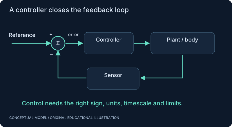
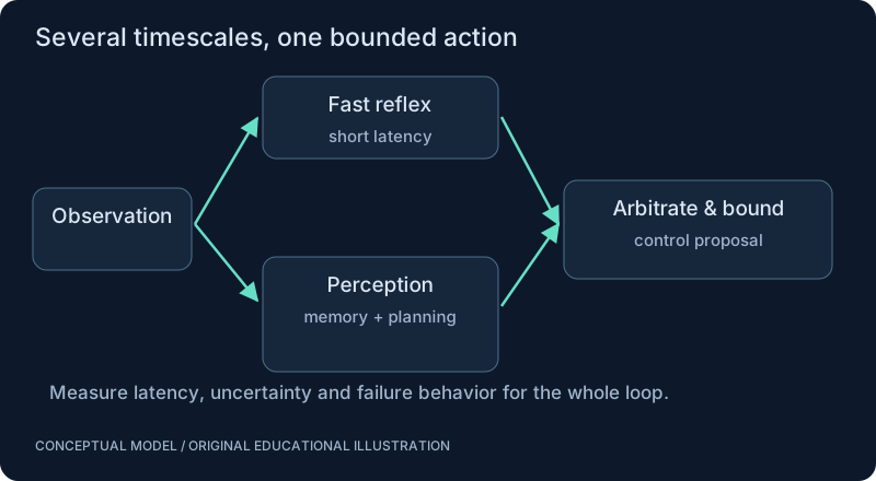
A neural visual model can request a bounded maneuver while an autopilot maintains attitude and other fast control responsibilities. PX4 simulation documentation provides an engineering starting point. A message protocol such as MAVLink transports data; it does not make an arbitrary neural value a safe or meaningful command. Units, frames, rates, authority and timeout behavior belong in the interface specification.
Neural-network perspective
Think of the neural stage as one source of task information in a larger closed loop. A looming signal may request braking, but the controller must reconcile it with state estimates and motion limits. Test latency, stale observations, dropped messages and conflicting requests in simulation. The following hover calculation does not send commands or validate a flight controller.
SEE THE RELATIONSHIPS
From structure to behavior.
MAKE THE IDEA PRECISE
The mathematics.
| Symbol | Meaning |
|---|---|
| T_total | Total ideal hover thrust, newtons |
| T_per_motor | Equal thrust per motor in this idealization, newtons |
| m | Vehicle mass, kilograms |
| g | Chosen gravitational acceleration, meters per second squared |
Build the equation, step by step
- For an ideal stationary hover, net vertical force is zero. Upward total thrust balances downward weight mg.
- Assuming four equally loaded vertical motors, divide total thrust by four. This gives force in newtons, not a throttle percentage.
- Tilt, acceleration, asymmetric loading and aerodynamic interactions invalidate equal static sharing. A flight controller needs an actuator model and attitude dynamics to translate force requests into motor commands.
WORK THROUGH THE NUMBERS
Worked example
For an illustrative 0.5 kg vehicle with g = 9.81 m/s², total ideal hover thrust is 4.905 N and each equally loaded motor contributes approximately 1.226 N. This ignores dynamics and is not a motor-selection specification.
A small Python experiment.
Python 3 · Standard library only · Synthetic educational example. Run this in your own notebook or a local file.
mass, gravity = 0.5, 9.81
total = mass*gravity
print(f"total = {total:.3f} N; per motor = {total/4:.3f} N")
Expected output
total = 4.905 N; per motor = 1.226 N
Change one quantity, predict the result, and then run the code again. Explain any difference before adding complexity.
Test your understanding.
Try it: Increase the modeled mass by 20%. What changes in the hover calculation, and what remains unknown?
Self-check: Does mg/4 specify the correct motor command?
No. It specifies an ideal force requirement. Mapping that requirement to electrical commands depends on the propeller, motor, battery, air conditions and calibrated controller. The example is a force balance, not a flight procedure.
Where this model stops: Physical flight needs independent hardware and safety validation. A simulated reflex is not flight-readiness evidence.
A research question: How does communication delay change avoidance success while the autopilot itself remains stable?
Record evidence in your mastery worksheet →THE NEXT LAYER
Chapter depth map.
This introduction provides a first model. The following chapters are outlines for deeper future editions; their full treatments have not yet been published.
Flight fundamentals
14.1 Quadrotor physics · Outline
- 14.1.1 Motors, ESCs, propellers and thrust
- 14.1.2 Forces, torques and center of mass
- 14.1.3 Roll, pitch, yaw and coordinate conventions
- 14.1.4 Attitude and position control loops
- 14.1.5 IMU, actuator saturation and state estimation
14.2 Autopilot interfaces · Outline
- 14.2.1 PX4 and ArduPilot responsibilities
- 14.2.2 MAVLink messages versus control semantics
- 14.2.3 Setpoint frames, units and timeouts
- 14.2.4 Software-in-the-loop and simulated sensors
- 14.2.5 Heartbeats, failsafes and control authority
Neural reflex experiments
14.3 A simulated fly-inspired interface · Outline
- 14.3.1 Event or frame input and visual processing
- 14.3.2 SNN activity and bounded reflex output
- 14.3.3 Arbitration with navigation commands
- 14.3.4 Latency budgets and stale observations
- 14.3.5 Log the entire sensor-to-control path
14.4 Validation gates · Outline
- 14.4.1 Scenario coverage and controller baselines
- 14.4.2 Dropout, delay and noise injection
- 14.4.3 Recovery and emergency-stop behavior
- 14.4.4 Hardware testing requires a separate safety review
- 14.4.5 No flight-readiness claim from a browser demonstration
Read with the original sources.
These readings support the concepts and deeper investigation. The worked numbers and illustrations above are teaching examples.
Official engineering documentation
PX4 — official simulation guide ↗
Begin with simulation and versioned interfaces. Simulation success alone does not establish hardware flight readiness.
Engineering repository; not independent validation
FlyDrones — upstream repository and limitations ↗
The README describes the browser MiniFly as synthetic and hand-wired. It identifies engineered sensory/readout mappings and says hardware adapters have not been flight-tested by its authors. No reproduction is claimed here.