What you will learn
Process a synthetic event stream and compare its information and cost with frame sampling.
Before you begin: Biological vision; Spiking neural networks
The sensor reports change
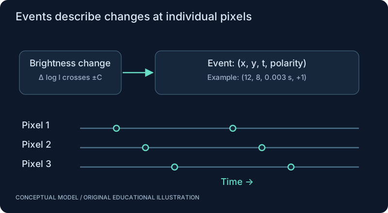
An event camera reports asynchronous brightness-change events at individual pixels. A common representation is (x, y, t, p): pixel location, timestamp and polarity. A simplified model triggers when a log-intensity change crosses a contrast threshold. An event is a sensor report, not a biological spike, even when an SNN consumes it directly.
Choose the representation by the deadline
You can feed events directly into a temporal model, accumulate a time surface, or form bins resembling frames. Binning makes conventional tensor processing convenient but introduces a windowing choice. Large windows may hide the latency advantage you wanted. Noise filtering and clock alignment matter before learning begins.
Neural-network perspective
An event stream provides sparse updates when scene brightness changes locally. The model still needs a state representing recent events. A polarity-aware encoder can separate increases from decreases; a decoder maps activity to task outputs. If a task depends on static texture or absolute intensity, inspect what the event representation fails to provide.
The fair comparison
Compare complete sensor-to-answer systems using the same scene, task and required accuracy. Measure missed events, spurious events, backlog and end-to-end delay. High temporal resolution at the sensor does not guarantee a low-latency software pipeline.
SEE THE RELATIONSHIPS
From structure to behavior.
MAKE THE IDEA PRECISE
The mathematics.
| Symbol | Meaning |
|---|---|
| I_new, I_ref | Positive intensity values on a common scale |
| L | Log intensity |
| C | Illustrative contrast threshold, dimensionless |
| p | Polarity: sign of the threshold crossing |
Build the equation, step by step
- Use log intensity so a multiplicative brightness ratio becomes an additive change: ln(I_new) − ln(I_ref) = ln(I_new/I_ref). Intensities must be positive.
- Compare the magnitude with the contrast threshold C. The sign determines event polarity when the threshold is crossed.
- A real event stream also depends on reference updates, timestamp resolution, refractory behavior and noise. The one-comparison example does not reconstruct all events that might occur during a large brightness jump.
WORK THROUGH THE NUMBERS
Worked example
An intensity rise from 100 to 130 gives ln(1.3) = 0.262. With a chosen threshold of 0.2, a simplified single-crossing rule emits a positive event. A real sensor may emit multiple events or exhibit noise and refractory effects.
A small Python experiment.
Python 3 · Standard library only · Synthetic educational example. Run this in your own notebook or a local file.
from math import log
change = log(130/100)
threshold = 0.2
polarity = 1 if change >= threshold else -1 if change <= -threshold else 0
print(f"change = {change:.3f}; polarity = {polarity}")
Expected output
change = 0.262; polarity = 1
Change one quantity, predict the result, and then run the code again. Explain any difference before adding complexity.
Test your understanding.
Try it: Try 100 to 80 and 100 to 110. Predict polarity and whether the threshold is crossed.
Self-check: Does an event camera report an absolute image at every timestamp?
No. Its events primarily describe brightness changes at particular pixels. Recovering a frame or inferring motion requires temporal state and assumptions; a quiet pixel is not proof of a dark pixel.
Where this model stops: This threshold example is not a calibrated event-camera simulator.
A research question: When does event filtering remove useful fast motion along with noise?
Record evidence in your mastery worksheet →THE NEXT LAYER
Chapter depth map.
This introduction provides a first model. The following chapters are outlines for deeper future editions; their full treatments have not yet been published.
Sensor and representation
9.1 An asynchronous camera · Outline
- 9.1.1 DVS and the event tuple (x, y, t, p)
- 9.1.2 Log-intensity contrast thresholds
- 9.1.3 Polarity, timestamp precision and refractory effects
- 9.1.4 Latency, dynamic range and noise
- 9.1.5 Limits in static scenes and low contrast
9.2 From events to features · Outline
- 9.2.1 Event filtering and temporal windows
- 9.2.2 Time surfaces and voxel representations
- 9.2.3 Direct event-to-spike mapping versus frame conversion
- 9.2.4 Reconstruct synthetic motion with ground truth
- 9.2.5 Avoid treating an event as a biological action potential
Systems and comparisons
9.3 Event stream to action · Outline
- 9.3.1 Event camera to encoder to SNN
- 9.3.2 Optional circuit-inspired stage
- 9.3.3 Activity decoding into bounded commands
- 9.3.4 Clock synchronization and processing backlog
- 9.3.5 Simulation before sensor purchase
9.4 Is the event camera justified? · Outline
- 9.4.1 Matched camera-plus-CNN baseline
- 9.4.2 Whole-pipeline latency and energy
- 9.4.3 Flicker, vibration and hot-pixel stress tests
- 9.4.4 Dataset provenance and leakage
- 9.4.5 Report regimes where conventional frames win
Read with the original sources.
These readings support the concepts and deeper investigation. The worked numbers and illustrations above are teaching examples.
Author manuscript / survey
Gallego et al.: Event-based Vision, A Survey ↗
A field map for sensing, representations and algorithms. Follow its cited primary experiments before asserting an application advantage.