What you will learn
Produce a source-to-behavior trace that labels simulation, model assumptions, and biological evidence separately.
Before you begin: Drosophila: anatomy, circuits & datasets; Spiking neural networks; Biological vision
Separate the demonstration from the evidence
FlyDrones is an engineering case study connecting visual features, a spiking model and an action interface. Its upstream README identifies browser MiniFly as synthetic, distinguishes real-connectome modes, and describes engineered sensory/readout mappings. This book has not reproduced the repository or flight-tested hardware. A compelling animation must not be substituted for that evidence.
Follow the engineered bridge
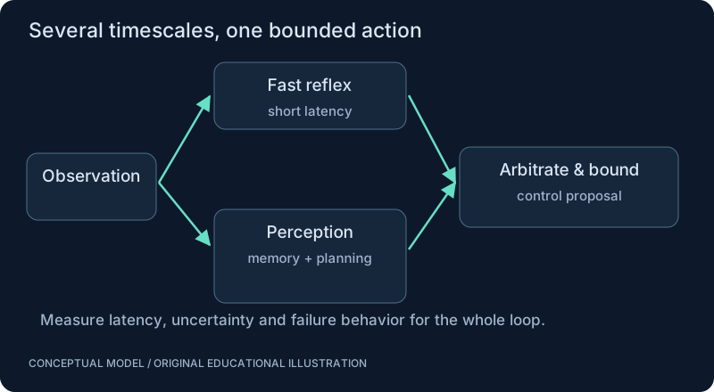
Audit the pipeline from camera processing through model inputs, neural state, activity readout and command constraints. The project documentation describes a simulator and safety-related components. Record a repository commit before analyzing exact functions; a moving branch is not a reproducible experimental specification. The diagram here represents the categories to inspect, not verified line-by-line source behavior.
A decoder is a design decision
Suppose a toy model emits left and right activity estimates. Their difference can request a turn. A gain converts neural units into controller units, and saturation enforces a bound. These transformations are supplied by the engineer. The example below is an original illustration of that interface, not an extracted FlyDrones implementation.
Test what caused the behavior
Use the same camera stream and controller while replacing the neural model with a simple baseline, shuffled wiring or a matched-rate surrogate. If performance is unchanged, the demonstration has not isolated a benefit from biological structure. Stability supplied by the autopilot also must be separated from the neural model’s contribution.
SEE THE RELATIONSHIPS
From structure to behavior.
MAKE THE IDEA PRECISE
The mathematics.
| Symbol | Meaning |
|---|---|
| r_right, r_left | Illustrative right/left activity rates, Hz |
| k | Decoder gain, controller units per Hz |
| u_max | Maximum magnitude of requested yaw command |
| clip | Clamp a value to a stated interval |
Build the equation, step by step
- Form a signed difference between the right and left readout. Reversing their order reverses the proposed turn direction.
- Multiply by a gain whose units convert readout units into the chosen command unit. A dimensionless score is not automatically radians per second.
- Clip the result to an explicit permitted interval. Clipping bounds a number but does not prove stability, obstacle avoidance or safe actuation.
WORK THROUGH THE NUMBERS
Worked example
Let right activity be 40 Hz, left activity 20 Hz, and gain 0.01. The unbounded request is 0.2 controller units. A chosen limit of 0.15 clamps it to 0.15. No motor command is sent.
A small Python experiment.
Python 3 · Standard library only · Synthetic educational example. Run this in your own notebook or a local file.
left, right, gain, limit = 20, 40, 0.01, 0.15
request = gain*(right-left)
bounded = max(-limit, min(limit, request))
print(f"request = {request:.2f}; bounded = {bounded:.2f}")
Expected output
request = 0.20; bounded = 0.15
Change one quantity, predict the result, and then run the code again. Explain any difference before adding complexity.
Test your understanding.
Try it: Reverse left/right activity and explain the sign convention. Then set the two rates equal.
Self-check: Why is a connectome-derived label insufficient to validate a flight controller?
The behavior also depends on input encoding, neuron dynamics, output decoding, gains and the downstream controller. Each engineered interface can dominate the result. Validate them in a stated simulation before considering any hardware experiment.
Where this model stops: This is a documented conceptual audit and a separate toy decoder, not a verified reproduction of upstream software.
A research question: Which ablation would isolate the value of topology from encoder and decoder design?
Record evidence in your mastery worksheet →THE NEXT LAYER
Chapter depth map.
This introduction provides a first model. The following chapters are outlines for deeper future editions; their full treatments have not yet been published.
Audit before interpretation
10.1 Repository, model and provenance · Outline
- 10.1.1 Pin a repository commit and inspect configuration
- 10.1.2 MiniFly synthetic network versus real-data modes
- 10.1.3 Neuron dynamics and connection transformations
- 10.1.4 Which camera features enter which cell groups
- 10.1.5 Inventory source files and distinguish claims from reproduced results
10.2 Trace one approaching object · Outline
- 10.2.1 Pixels or events and motion estimates
- 10.2.2 T4/T5-labelled input and looming representations
- 10.2.3 LPLC2, LC4 and DNp01-labelled activity
- 10.2.4 Spike propagation and descending readout
- 10.2.5 Decoder, safety governor and simulated drone response
Test the engineered bridge
10.3 Equations and implementation audit · Outline
- 10.3.1 Write units for every signal conversion
- 10.3.2 Identify LIF parameters, delays and thresholds
- 10.3.3 Derive readout scaling and saturation
- 10.3.4 Distinguish anatomy from hand-designed mappings
- 10.3.5 Log one end-to-end stimulus with timestamps
10.4 What the demo establishes · Outline
- 10.4.1 MiniFly ablations and shuffled wiring controls
- 10.4.2 Separate controller stability from brain-model outputs
- 10.4.3 Compare a conventional motion-to-control baseline
- 10.4.4 Reproduce claims before adopting them
- 10.4.5 No inference from a demo to general intelligence
Read with the original sources.
These readings support the concepts and deeper investigation. The worked numbers and illustrations above are teaching examples.
Engineering repository; not independent validation
FlyDrones — upstream repository and limitations ↗
The README describes the browser MiniFly as synthetic and hand-wired. It identifies engineered sensory/readout mappings and says hardware adapters have not been flight-tested by its authors. No reproduction is claimed here.
Primary paper
Shiu et al. (2024): a Drosophila computational brain model ↗
A connectome-based computational model of sensorimotor processing. Separate experimentally tested predictions from the model assumptions and untested behaviors.
Primary engineering documentation
FlyDrones — upstream architecture documentation ↗
Describes the engineered processing pipeline; repository claims have not been independently reproduced here.
Primary engineering documentation
FlyDrones — upstream science and assumptions ↗
Consult alongside the biological papers; labels and interfaces in a model do not establish biological equivalence.